A bracket was made smaller and its estimated unit cost fell from 17.22 EUR to 14.69 EUR, under a 16 EUR target, yet it was still rejected. The DFM review also found that, on the seating side of two M5 base holes, the stiffening ribs leave no room for the screw head and its hex key; and without any DFM requirement, this variant already fails the hole-edge-distance check. That is the verdict pai-design-workbench’s 3-axis milling design-for-manufacturing (DFM) check returns in the project’s own end-to-end test. Working from the source at a pinned commit, this article shows how the check derives setup count, hole drillability, fastener clearance and a unit-cost estimate from the B-Rep geometry, and under which model and assumptions each result holds.
It relies on four files pinned at commit d095382: the check script native/cad_dfm.py, the shop parameters native/dfm-shop.json, the end-to-end test scripts/cad-e2e.ts and the requirements table docs/REQUIREMENTS.md ([O], the project’s own account). The figures 17.22 EUR and 14.69 EUR come from the acceptance record for F21 in the requirements table; the test script only asserts how they compare with 16 EUR. This site did not run CadQuery, the test or any solver, and did not verify the shop parameters. How the same repository mounts an accepted part on a robot-arm simulation is covered in Carrying an accepted CAD part into a robot arm simulation: mass checks and portable MJCF and OpenUSD exports; this article is about a different gate that comes before acceptance: whether the part can be made on a 3-axis mill, and roughly what it costs.
One saved comparison: the reference part is over budget, the compact part cannot take its screws
The test project is a NEMA 17 motor-mount bracket, and its stated decision is “accept a lighter bracket only if wall, interface and assembly checks still pass”. The DFM section uses the reference part as the baseline and the compact variant as the candidate, and adds dfm: { maxSetups: 2, maxUnitCostEur: 16 } to the requirements of that review. The results asserted by the test and recorded in the requirements table:
| Check | Reference (baseline) | Compact (candidate) | Requirement |
|---|---|---|---|
machining-setups | not asserted by the test | 2 (test comment: +Y face, +Z base) | ≤ 2 |
unit-cost | 17.22 EUR, failed | 14.69 EUR, passed | ≤ 16 EUR |
fastener-access | passed; M5 and M3 screws both seat | 2 holes blocked, failed | 0 |
| Verdict of this review | — | rejected | — |
A test comment gives the reason: with width W = 50, the side ribs (x ≥ 21) overhang the fixed M5 base holes (x = ±20, Ø5.5), so an M5 head cannot seat. Note that in the same test, without the DFM requirement, compact is already rejected for hole-edge-distance. The DFM section asserts only the items above and does not list every failed check, so the rejection cannot be attributed to fastener clearance alone.
Setup count: an exact cover over six principal directions
The script imports the STEP file with CadQuery and walks the B-Rep faces: for a plane it records the outward normal n; a concave cylindrical face (face orientation TopAbs_REVERSED) is recorded as a hole, with its diameter, its depth along the axis and the axis direction. Only the six principal tool directions d, ±X, ±Y and ±Z, are considered. A plane is reachable from d if n·d ≥ 0, meaning end milling (normal facing the tool) or side milling (normal perpendicular to the tool axis); a hole is reachable from one end if the drill corridor beyond that end contains no material. The script tries every combination of 1 to 6 directions in order of size, and the first one that covers all planes and holes becomes the set of setup directions. With only six candidates the exhaustive search is an exact set cover.
That exactness holds only inside its own accessibility model. Following the code one step further shows how permissive the model is: an axis-aligned plane counts as reachable from five of the six directions, every one except the direction opposite its normal. So as long as all of a part’s planes are axis-aligned, any two different directions cover every plane; only hole corridors or sloped faces can require a third. The script’s docstring also states that occlusion of planar faces by other parts of the part is not modelled, and every oblique hole is treated as unreachable. Tool length, fixturing and workholding are not counted either.
One more point: the code treats every concave cylindrical face as a hole, which then counts towards the hole count, the drilling time and the depth-to-diameter check. A larger bearing bore or a concave fillet, being a concave cylindrical face, would be counted the same way; the supplied material does not show how this bracket’s faces were classified.
Holes and screws: two cylindrical probes
Both checks use the same method: place a cylindrical probe along the hole axis just beyond one end of the hole and intersect it with the part; an intersection volume above 0.001 mm³ counts as blocked. They differ in probe size and in which end they look at:
- Drillability (
hole-drillability): the probe radius is 0.98 times the hole radius, and its length is 30 mm (drillAccessMm). A hole is drillable if either end is clear; a hole blocked at both ends cannot be drilled. The depth-to-diameter ratio, hole depth divided by diameter, is compared with the shop limit of 4.0; a hole whose depth cannot be determined also counts as over the limit. - Fastener clearance (
fastener-access, DFA): a hole whose diameter is within 0.05 mm of a clearance diameter indfm-shop.jsonis taken as the clearance hole for that screw (3.4 → M3, 5.5 → M5, 9.0 → M8, ISO 273 medium). The probe diameter is the head diameter plus 1 mm, and its length is the head height plus the key access (ISO 4762 socket head cap screws). The seating side is the end that does not lie on the part’s bounding box, that is, the end away from the datum or mating face; if both ends or neither do, either end is accepted.
Take M5 and work out the probe from the shop parameters: head diameter 8.5 mm, head height 5 mm, key access 20 mm, so the probe radius is 8.5 / 2 + 0.5 = 4.75 mm and its length 5 + 20 = 25 mm. With the hole centre at x = 20, the probe spans x = 15.25 to 24.75 mm, which overlaps the ribs at x ≥ 21 described in the test comment. This is this site’s geometric arithmetic from the parameters, not a new run. Because the two checks follow different rules, the same hole can be drilled from the datum side while the screw still cannot seat on the other side.
The cost estimate: every term comes from dfm-shop.json
The structure of the estimate is in the script and the parameters are in the shop file, whose comment calls them “rule-of-thumb values for 6061-T6 on a small VMC” and says to change them there, not in code:
# values from dfm-shop.json substituted; lengths in mm, area in mm²
stock_cm3     = (bb.xlen + 2*2.0) * (bb.ylen + 2*2.0) * (bb.zlen + 2*2.0) / 1000
material      = stock_cm3 * 2.7 / 1000 * 6.5          # EUR
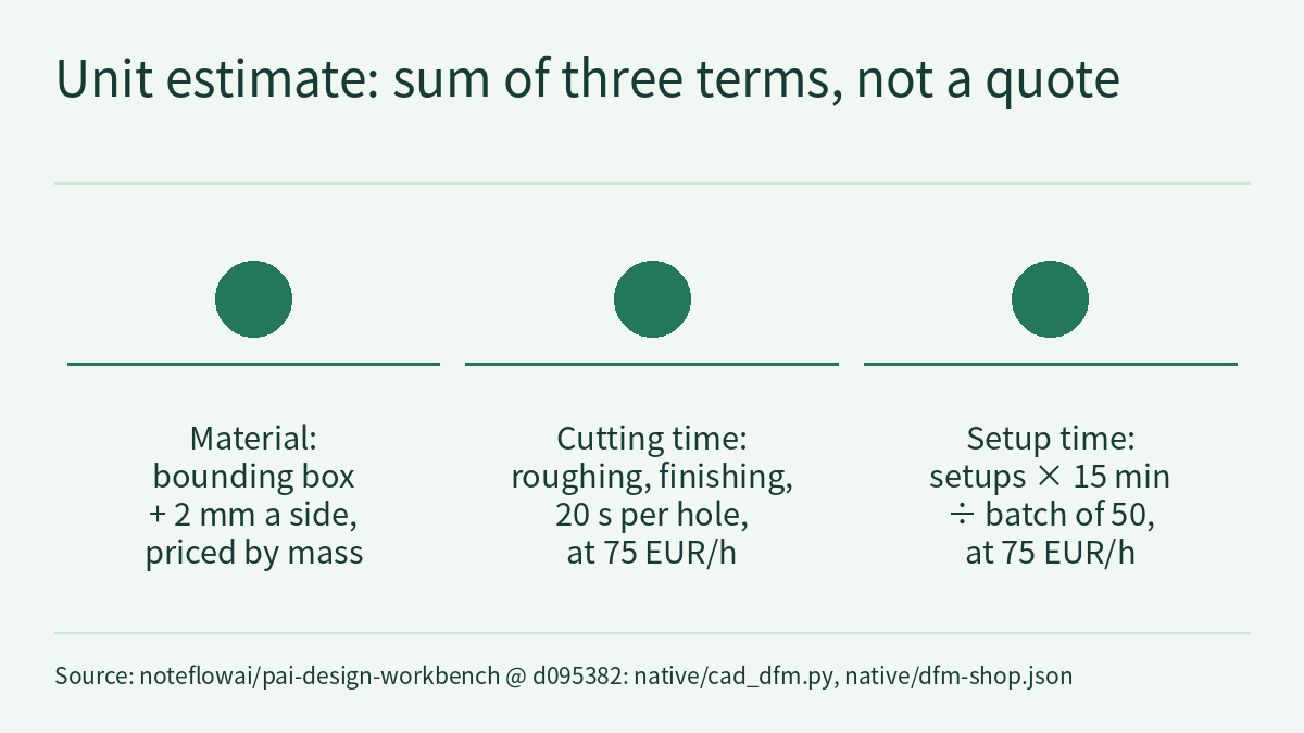
minutes       = (stock_cm3 - part_cm3) / 20 + (area / 100) / 25 + len(holes) * 20 / 60
setup_minutes = setups * 15
unit          = material + (minutes + setup_minutes / 50) / 60 * 75   # EUR
This is the script’s formula with the shop parameters substituted: 2.0 mm allowance, density 2.7 g/cm³, material 6.5 EUR/kg, roughing 20 cm³/min, finishing 25 cm²/min, 20 s per hole, 15 min per setup, batch 50, machine time 75 EUR/h.
The script’s output also writes the stock volume, the part volume, the stock-to-part volume ratio (buyToFly), the machining minutes and the material cost, so each term can be checked, and the check description states “not a quote”.
The two calculations below are this site’s arithmetic from the formula, to show the size of each term; they are not measurements. First, the test asserts a nominal bounding box of 60 × 30 × 50 mm for the reference part. If the DFM uses the same bounding box, the stock is 64 × 34 × 54 mm = 117.504 cm³, about 317 g, and the material cost about 2.06 EUR. The remaining roughly 15.16 EUR of the 17.22 EUR is machine time, about 12.1 minutes at 75 EUR/h (including the allocated setup time). Under these assumptions, then, the reference part exceeds 16 EUR mainly because of machine time, not material. Second, at a batch of 50 each setup adds 15 ÷ 50 = 0.3 minutes, about 0.375 EUR, per part; if the batch assumption were 1, each setup would cost 18.75 EUR, and two setups alone would exceed 16 EUR. The outcome of the cost gate depends directly on assumptions such as batch size and rates, and a different shop needs a different parameter file.
Entering the review as a frozen requirement
Requirement F21 describes DFM as an “optional frozen requirement” that feeds the CAD checks and EvalArc. In the test, the DFM thresholds are submitted with the requirements of that one CAD review request; the project’s own acceptance criteria are unchanged. The script’s defaults also show that it is optional: without maxSetups the limit is 3, and without maxUnitCostEur the limit is 10⁹ EUR, which amounts to no cost gate.
The thresholds have to be set before the review, not adjusted after seeing the result. Another section of the same test demonstrates the rule: when fixing a wall-thickness issue, a recheck request that relaxes minWallMm to 2 makes the review fail with INVALID_RECHECK. That section concerns wall thickness, not DFM, but the practice carries over to the cost gate: freeze maxUnitCostEur and the shop parameters first, then compare candidates.
One result is reported but does not gate: sharp internal corners. A 3-axis milled internal corner keeps the tool radius; the script counts concave edges that cannot be made sharp from the chosen directions, and in notes suggests a corner radius of at least 1.5 mm (half the 3.0 mm minimum tool diameter) or EDM. It is not one of the four checks and does not affect the verdict.
Limitations
- The cost is an estimate from the rule-of-thumb parameters in the shop file. It is not a quote, not a production measurement, and not a guaranteed saving from a design change. Requirement F21 states that no CAM toolpath simulation was performed; the repository has a separate CAM check under F29, which this article does not cover.
- The setup cover is exact only within the model of “six principal directions,
n·d ≥ 0, planar-face occlusion not modelled”; it does not establish that the part is manufacturable in general. Curved surfaces, tool length, workholding and tolerances are outside the model. - 17.22 EUR, 14.69 EUR and “2 setups” are development results reported by the project, and the test assertions are checks the project wrote itself; this site did not independently run native CAD or measure shop cutting rates or cycle times. The split into material and machine time above assumes that the DFM uses the same bounding box as the reference part.
- Without the DFM requirement, the compact part is already rejected for hole edge distance, so the verdict of the DFM section cannot be attributed to fastener clearance alone.
- The test report records
physicalValidation: false,feaPerformed: falseandtoleranceStackUp: false. The part is nominal geometry only, and nothing in this article is a strength or physical safety conclusion. The requirements table also lists “treating simulation as physical validation” as out of scope.
Links
- Check script: native/cad_dfm.py (commit d095382)
- Shop parameters: native/dfm-shop.json (commit d095382)
- End-to-end test: scripts/cad-e2e.ts (commit d095382)
- Requirements and acceptance status: docs/REQUIREMENTS.md (commit d095382)
- Related on this site: Carrying an accepted CAD part into a robot arm simulation: mass checks and portable MJCF and OpenUSD exports
- Related on this site: Checking an agent’s physics estimate against held-out solver results: the evaluation passed, but the height trend was backwards