A bracket has passed the geometry and finite-element checks of a CAD review. The next question is whether, once mounted on the end of a robot arm, the workcell can still complete its pick-and-place within the cycle time and without collisions. The physics lane of pai-design-workbench answers that with MuJoCo, but it first establishes that the part being mounted is the one that was accepted and that its mass has been computed correctly, and then exports the simulated scene as MJCF and OpenUSD that can be reopened elsewhere. Based on docs/PHYSICS.md, native/robot_sim.py and a saved demo record, docs/evidence/physics-demo.json, pinned at commit 70330e2, this article goes through what each step of the path from CAD to robot simulation checks, and what it cannot check.
All numbers here come from the project’s own documentation, code and records ([O], self-reported by the project). This site did not run these tests and did not reproduce the demo. The aerodynamics lane of the same repository is covered in Carrying a pinned OpenFOAM case to AWS Batch: hashed results, two meshes and a drag comparison with the local run. This article does not discuss how the bracket was optimised, only what happens once the part enters the workcell.
What the workcell simulation tests
robot_sim.py accepts no user-supplied XML. It takes eight bounded parameters and generates the MJCF model itself; any value out of range stops the run:
| Parameter | Allowed range |
|---|---|
pickDistance, placeDistance | 0.25–1.1 |
pickHeight, placeHeight | 0.6–1.2 |
pedestalHeight | 0.3–1.0 |
guardClearance | 0.1–1.5 |
speedFraction | 0.1–1.0 |
jitter | 0.0–0.08 |
The parameter ranges above are reproduced from the source, whose range definitions do not annotate units. The documentation specifies metres for guard clearance; speedFraction is a fraction of rated joint speed.
The scene contains a generic 6-axis arm on a pedestal, with link lengths taken from the dimensions in the public UR5e datasheet (UR5e-class), plus a conveyor pick station, a fixture place station and four guard panels. The documented standard run uses 10 fixed seeds, each adding a seeded offset to the pick pose. For every seed it does three things: inverse kinematics by damped least squares on the MuJoCo Jacobian, within joint limits; a joint-space quintic trajectory at a configured fraction of rated joint speed, through approach, pick, lift, transfer, place and retract; and position actuators driven with full rigid-body dynamics at 500 Hz, while detecting contacts between the arm links and the static scene (the gripper’s intended contact with the picked workpiece is excluded). The four checks are:
reach: TCP error ≤ 2 mm at pick and place, for every seed. The documentation describes this check in terms of pick and place. The code runs damped least squares within the joint limits for at most 400 iterations per target and takes the worst TCP error across all six inverse-kinematics targets, including approach and lift points 0.12 m above pick and place. The check fails whenever that worst error exceeds 2 mm. That can happen because the target lies outside the workspace, which is the “there may be no solution” case from Physical AI Lab 1.1: Coordinate Frames and Kinematics — Working Out by Hand How a Two-Link Arm Reaches the Cup; it can also happen because the iteration did not converge although a solution exists. The check does not distinguish the two.collision-free: no arm-link contact with the guards, the conveyor frame or the fixture during the motion.cycle-time: the slowest seed’s cycle, including settling, is ≤maxCycleSeconds.success-rate: the share of seeds that reach, stay collision-free and meet the cycle is ≥minSuccessRate.
The reference cell and the candidate cell run the same seeds, the interface lists the results seed by seed in pairs, and a seed that succeeded in the reference but failed in the candidate is flagged. This is the same paired approach as Robot Reel. PHYSICS.md records the result of npm run test:robot after raising the target to a 5-second cycle:
| Cell | Result |
|---|---|
| Reference, 50 % speed | 5.90 s, fails the new target |
| 75 % speed, guards pulled in to 0.12 m | 4.60 s, but the elbow hits the guard on every seed: rejected |
| Same speed, guards at 0.30 m | 4.60 s, 10/10 seeds succeed: accepted (22 % faster than the reference) |
The saved demo record, physics-demo.json, is a separate run recorded on the project’s hosted site, not the npm run test:robot result in the table above; its values round to the table’s: the rejected cell’s cycle was 4.598 s with 0 of 10 seeds collision-free (0/10); the reference took 5.897 s; the fix changed a single setting, guardClearance 0.12 → 0.3, and requirementsRelaxed is false, meaning the requirements were not loosened. (5.897 − 4.598) / 5.897 ≈ 0.22, consistent with the recorded 22 %. The record names the engine and model that proposed the fix, but its modelEvidence field is acp_advertised: the identity the engine declared for itself, not independently verified model provenance.
Mounting the part on the gripper: only the accepted copy
A workcell request may carry tool: { cadReviewId, payloadKg }. According to PHYSICS.md, the server accepts only a completed CAD review of the same project whose verdict is accepted, and checks the STL against the digest that review recorded; a part that is not accepted is refused with TOOL_NOT_ACCEPTED. robot_sim.py also recomputes the STL’s SHA-256 itself and stops if it differs from the digest in the script’s input spec (which the error message calls the CAD review record), and checks a payload of 0–3 kg, a motor-axis position of 5–120 mm and a B-Rep mass of 1–2000 g.
Once these pass, the exact STL is mounted on the gripper as a mesh body, and the declared payload is added at the motor axis (by default a 0.28 kg NEMA 17 motor; in the code, a box of the given mass). The reference cell and the candidate cell carry the same tool, so the comparison is between cells, not tools. The part’s collision shape counts toward collision-free: the code puts cad-tool on the arm side, so the part touching a guard is also a collision.
Three representations of one part
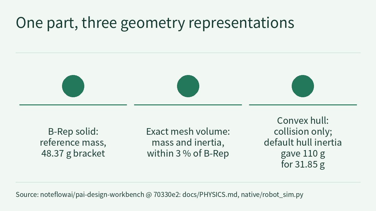
This is the part of the path most worth copying: in the simulation, one part has three geometric representations with different roles, and they must not be mixed up.
| Representation | Used for | Recorded figures |
|---|---|---|
| B-Rep solid (CAD review) | Reference mass | Reference bracket 48.37 g |
Exact mesh volume (inertia="exact", 2.70 g/cm³, non-convex) | Mass and inertia in MuJoCo | Reference bracket 48.37 g; more than 3 % from B-Rep fails the run |
| Convex hull | Collision shape only | The default convex-hull inertia once gave 110 g for a 31.85 g part |
According to the documentation, the last row is why the 3 % check exists: 110 g is about 3.5 times 31.85 g. The documentation attributes the discrepancy to the default convex-hull inertia, which is what the 3 % check exists to catch, but does not explain further why the hull inflates the mass about 3.5-fold. The lesson here is to read back the computed mass and compare it with the threshold. The code checks it by taking the total mass of the cad-tool body minus the payload as the mesh mass and comparing it with the B-Rep mass in the input spec; beyond 3 % it exits with “tool mass mismatch”.
Exports: what MJCF and OpenUSD each check
MJCF. scene.xml references tool.stl in the same directory and contains no local paths, so the whole directory can be copied elsewhere and reloaded. test:robot checks this.
OpenUSD. scene.usda is Z-up, in metres. Each MuJoCo body becomes a rigid body with MassAPI (mass, centre of mass, diagonal inertia, principal axes); mesh colliders are convex hulls; there are six revolute joints with limits, fixed joints for welded bodies (such as the part on the gripper), and an articulation root. The stage is reopened and every registered OpenUSD 26.8 UsdValidation validator runs on it, including the UsdPhysics rigid-body, joint, articulation and collider checks; any error or warning fails the run, and so does a count of non-fixed joints other than six.
Passing validation does not make it the same robot. The optional Newton cross-check (Newton 1.6, its own venv, CPU Warp, no GPU needed) imports scene.usda into Newton and loads scene.xml into MuJoCo. It requires a single articulation with 6 revolute joints, no orphan joints and the same body masses, and compares forward kinematics at the exported pose and at 32 seeded configurations within the joint limits: every body within 0.1 mm in position and 0.01° in orientation. The documentation records that the first run found two export bugs that every UsdValidation validator had passed:
- The articulation root sat on
base, which is not an ancestor of the flat bodies, so Newton refused every joint as an orphan. The root now sits on/Workcell. - Joint frames were taken at the pick pose, so joint angle 0 and the limits meant something different in USD than in MuJoCo. They now come from the model constants (the parent-relative body offset at joint angle 0).
After the fix: 33 configurations, worst position error 0.45 µm, orientation error 3.1·10⁻⁵ °, masses within 0.5 mg, in 4.8 s. This result is recorded separately as newton.json. It is export conformance and never changes the review verdict; it covers kinematics and mass only, and says nothing about whether the two engines agree on dynamics.
Reproducing it locally
Following PHYSICS.md, from the repository root at commit 70330e2:
npm run setup:physics                    # Gmsh, Optuna, scikit-learn and MuJoCo installed hash-locked; CalculiX from the signed Ubuntu archive
npm run setup:physics -- --with-newton   # optional: Newton 1.6, in its own venv
npm run test:robot
According to the documentation, setup:physics installs hash-locked pinned versions (MuJoCo 3.14.0 and others), and the install receipt .state/tools/physics-install-receipt.json records every .deb digest and the lock hash. The documentation says test:robot mounts the reference bracket (B-Rep 48.37 g, MuJoCo mesh 48.37 g) and checks that the MJCF is portable, that the USD has physics joints and an articulation root, and that a part that is not accepted is refused. The supplied material does not describe cloning the repository or installing the npm dependencies; the toolchain table does not say how OpenUSD itself is installed; and the documentation does not say whether test:robot includes the Newton check.
Each run writes robot.json (per-seed results, the four checks, the tool mass comparison), scene.xml, scene.usda and robot.glb; robot.json always contains "scope": "rigid-body-simulation" and "physicalValidation": false.
The demo record and the poster
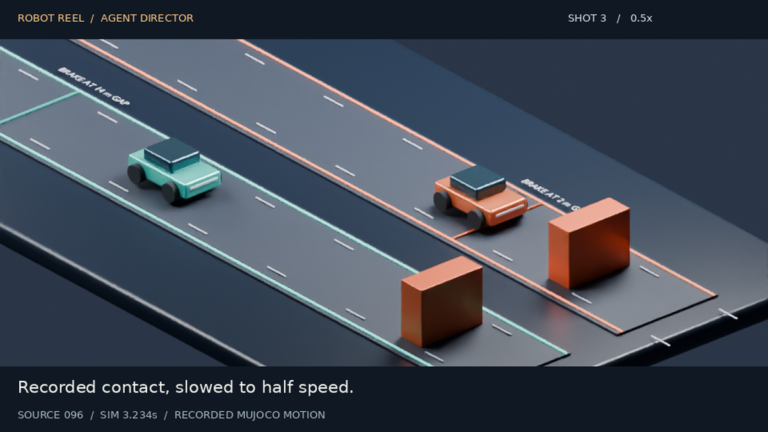
The cover of this article is the project’s physics demo poster. The demo record states that the screen recording is 659 seconds long at source, with nothing cut or reordered, and that visually static waits are played at 6× after 2.5 seconds; its chapters are requirements, MuJoCo, the AI-fixed cell, cell feedback, FEA, AI optimisation and release. Both feedback items in the record are closed (the scene’s collision-free and the part’s max-deflection), the part’s formal review verdict is accepted (46.87 g, 9/9 checks), and release R1 shows admission 5/5. The record does not show whether any CAD part was mounted in the demo’s workcell, and this article does not infer it; the accepted 46.87 g part comes from the FEA and AI optimisation chapters, which follow the MuJoCo and AI-fixed cell chapters. This is one demonstration recorded on the project’s hosted site, not an independent experiment and not a test on a physical robot.
Limitations
- The scope is a rigid-body simulation of a generic arm and a generic controller. The picked workpiece is attached kinematically when the gripper closes, with no grasp physics; the CAD bracket is a mesh body fixed to the gripper throughout the run. It is not the vendor’s controller, not a safety assessment and not a grasp-physics model. The link lengths are UR5e-class and do not represent the performance of any specific product.
- Part mass uses a nominal density of 2.70 g/cm³. On the FEA side the model is linear static, small deformation and nominal material, with no contact, bolt preload, fatigue, thermal effects, tolerances or test data. The results are simulation evidence, not certification.
- As a general geometric limitation of convex-hull approximations (our explanation), a hull encloses recesses and may therefore report a collision where the actual shapes would not collide. The saved project record does not verify a particular false-positive collision.
- The Newton check only shows that the exported kinematics and mass agree with MuJoCo. It does not show that dynamics behave the same in Isaac Lab or Newton.
- Figures such as 22 % and 0.45 µm are one recorded run in the project’s own environment; this site did not rerun them.
Links
- docs/PHYSICS.md: the physics lane (commit 70330e2)
- native/robot_sim.py: workcell simulation, tool mass check and MJCF/OpenUSD export
- docs/evidence/physics-demo.json: the saved demo record
- Original cover image: docs/media/physics-poster.png
- LICENSE (MIT)
- Carrying a pinned OpenFOAM case to AWS Batch: hashed results, two meshes and a drag comparison with the local run
- Physical AI Lab 1.1: Coordinate Frames and Kinematics — Working Out by Hand How a Two-Link Arm Reaches the Cup
- Robot Reel: turning robot policy simulations into frame-by-frame verifiable replays and 3D scenes
- Physical AI Lab: a physical AI course where every number can be checked (course outline)